Installing the Hands-Free for the
Crossfire Non-Navigation Factory Radio/CD player
Before removing
my factory radio/CD player, I installed the necessary wiring to
use a hands-free phone device. It was inexpensive and very
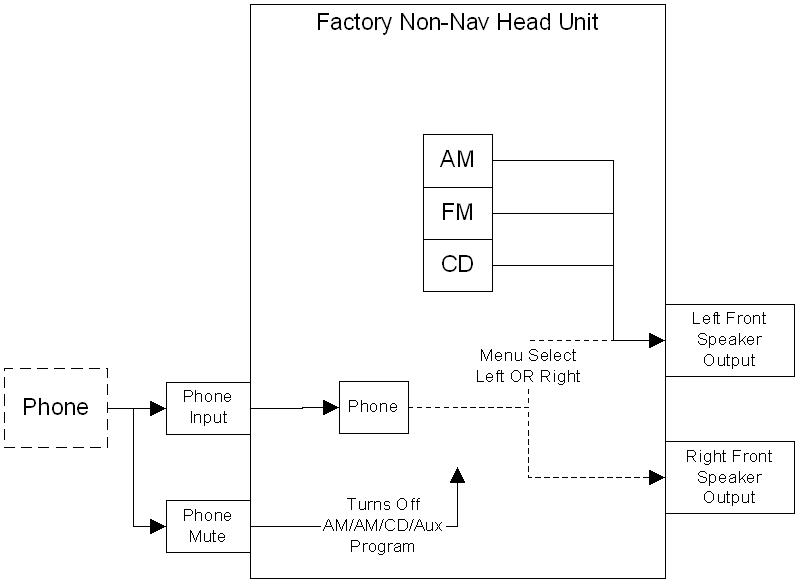
simple. Here is the general layout of connections for the
head unit.

An auxiliary input is
provided that gives
a mono connection for the cell phone system. (diagram).
One could use something like a Motorola
Bluetooth to route phone sound through the stereo and pause the
music to take or make a call. I highly recommend adding the
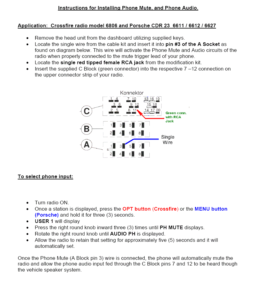
phone connection. (Instructions below are for the factory
unit installed in the Crossfire though the instructions refer to
Porsche which also have the same unit). I purchased the
wires needed (Part# BNA - 1319 - 116) from Becker USA,
online.
http://www.beckerautosound.com/Service.html
http://www.beckerautosound.com/chrysler_crossfire/index.html
Here are the
instructions they provided, (along with the radio removal tools
and wires). It's a ten minute job. You may need to
add an RCA connector to the sound output from the hands-free to
the radio.


| |
|
Becker Radio Connector (into car) |
Wires
(into aftermarket stereo) |
| Socket |
Pin |
|
Color |
|
|
| |
|
Socket A (power/modes) |
|
|
|
| A |
1 |
Speed Volume Control |
|
|
|
| A |
2 |
unused or reversing lamp signal |
|
|
|
| A |
3 |
telephone mute |
Blue/White |
|
|
| A |
4 |
permanent positive 12v (fuse terminal 30) |
Yellow * |
|
|
| A |
5 |
Amp/power antenna on |
Blue |
|
|
| A |
6 |
Illumination (fuse terminal 58d) |
Orange |
|
|
| A |
7 |
switched postive 12v (fuse terminal 15) |
Red * |
|
|
| A |
8 |
Ground (-) |
Black |
|
|
| |
|
|
|
|
|
| |
|
Socket B (speakers) |
|
|
|
| B |
1 |
RR (+) |
Violet |
|
|
| B |
2 |
RR (-) |
Violet/Black |
|
|
| B |
3 |
RF (+) |
Gray |
|
|
| B |
4 |
RF (-) |
Gray/Black |
|
|
| B |
5 |
LF (+) |
White |
|
|
| B |
6 |
LF (-) |
White/Black |
|
|
| B |
7 |
LR (+) |
Green |
|
|
| B |
8 |
LR (-) |
Green/Black |
|
|
| |
|
|
|
|
|
| |
|
RR - Right Rear |
|
|
|
| |
|
RF - Right Front |
|
|
|
| |
|
LF - Left Front |
|
|
|
| |
|
LR - Left Rear |
|
|
|
| |
|
|
|
|
|
| |
* |
Permanent Positive and switched positive |
|
|
|
| |
|
leads should be checked and wired based |
|
|
|
| |
|
on state measured coming out of car harness |
|
|
|


Visitors since
6/25/08